First let me tell you, I am not expert in VHDL, just recently I started working on CPLDs and it was very exciting and hence sharing this experience with you all.
Overview
CPLDs(or FPGA) are very interesting devices, you can put any digital circuit of your choice in them, provided it fits within available resources. We can implement simple circuits like adders, counters, PWM generators and even complex microprocessors on CPLDs ! In this tutorial we will implement simple MOD-4 counter and see how to use Xilinx’s XC9536 CPLD.
Tools and components
-
Xilinx ISE WebPack : This is free design solution from xilinx. We will use this to write VHDL code, synthesize it and then burn it on CPLD. Its huge package ~ 1.7GB. Download and install it.
-
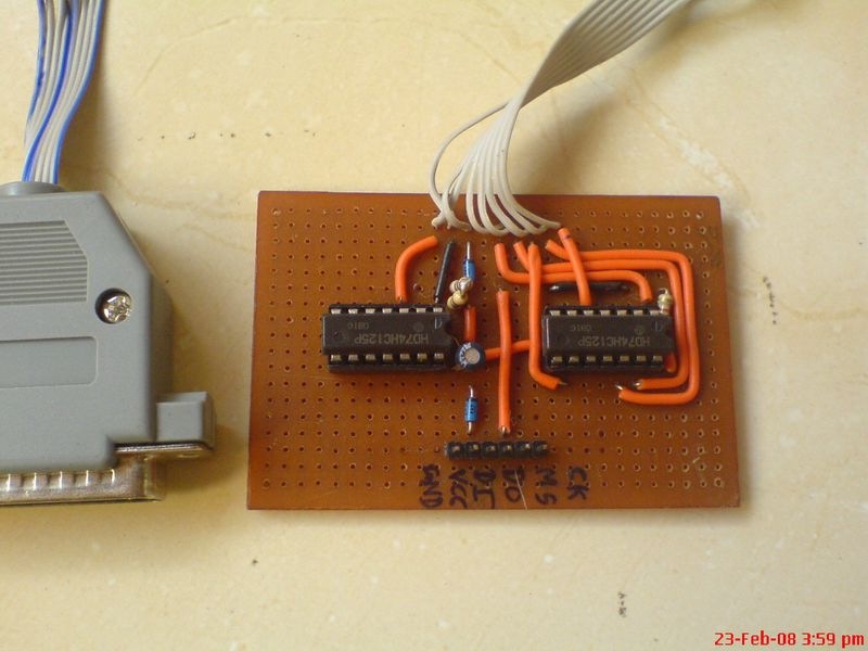
JTAG cable : We need this to burn our code into CPLD. This is the schematic diagram for the JTAG cable, I got it from net.


Ignore FPGA header part. You can also skip 300E resistors connected to D25 socket. Although my JTAG cable works fine without these resistors , I would advise to construct a cable as shown. Important : Length of the ribben cable between D25M connector and board should be less than 2Ft. -
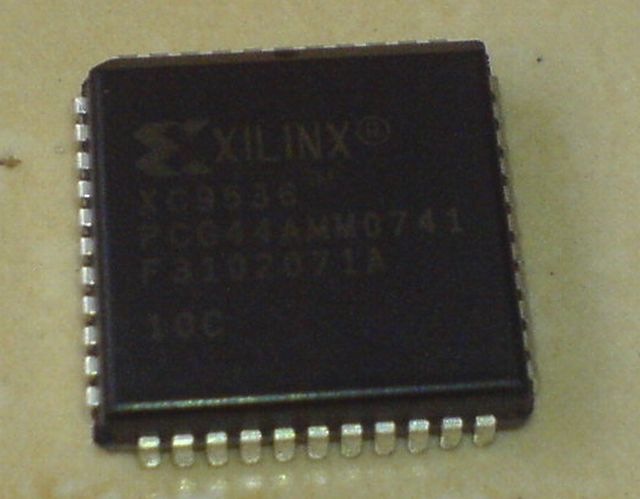
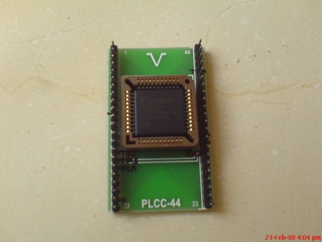
The CPLD XC9536 : Of course you need this! You can purchase it for around 180Rs. Do not purchase XC9536XL as it runs on 3.3V, it will be problematic at beginner level. Once you are familier with CPLDs, then you can go for XL devices.

-
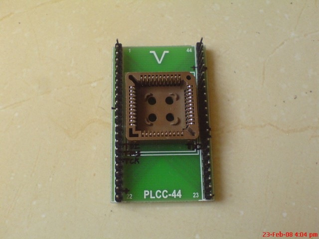
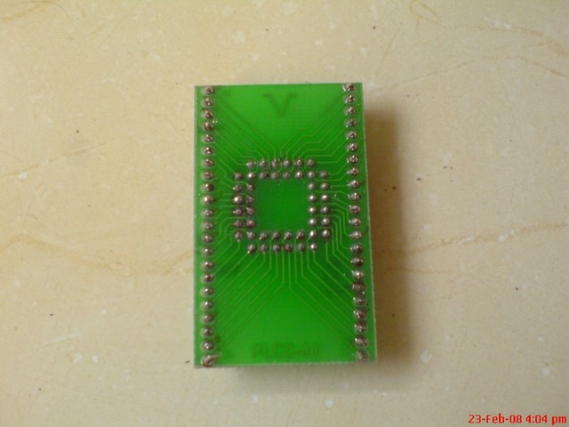
CPLD daughter board : You just can’t connect wires directly to CPLD. You have to put it in a PLCC socket. Again you can’t solder wires to this socket nor you can put it in Bread board. Thus you need ready made PCB for mounting PLCC44 socket or you have to make one at home. These PCBs are quite common and will be available in decent electronics shop.


- Few LEDs, 470E resistors, microswitch, 7805, 47uF caps and connecting wires.
Writing code for MOD-4 counter
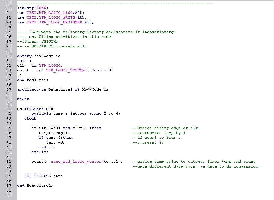
Mod4 counter has one input ‘clk’ and two outputs ‘count[0]’ and ‘count[1]’ . On rising edge of clock, counter will increment by 1. It goes through 00,01,10,11 states on successive pulses.
| I assume that you have downloaded and installed xilinx ISE WebPack. Now lets write the VHDL code for simple MOD-4 counter. | |
| This illustration shows how you can write the code in Xilinx ISE WebPack. Download it for proper viewing. |

Adding Constraints
Now, we have to add constraints to our design. By specifiying constraints we can assign suitable pins of XC9536 to input and output signals. We will assign Pin1 to clk, Pin2 to count[0] and Pin3 to count[1].
| This illustration shows how to specify constraints. Download it for proper viewing. |

Downloading code into XC9536
Once you have finished with above mentioned steps, now you are ready to download the code into device.
| Connect your CPLD to JTAG cable. i.e. connect TCK, TDI, TDO,TMS of JTAG cable to respective pins on CPLD. For XC9536 in PLCC44 package : TCK = pin17; TDI = pin15; TDO = pin30; TMS = pin16 |
|
| Now follow this illustration to download code into CPLD using iMTACT tool. Download it for proper viewing. |
Testing
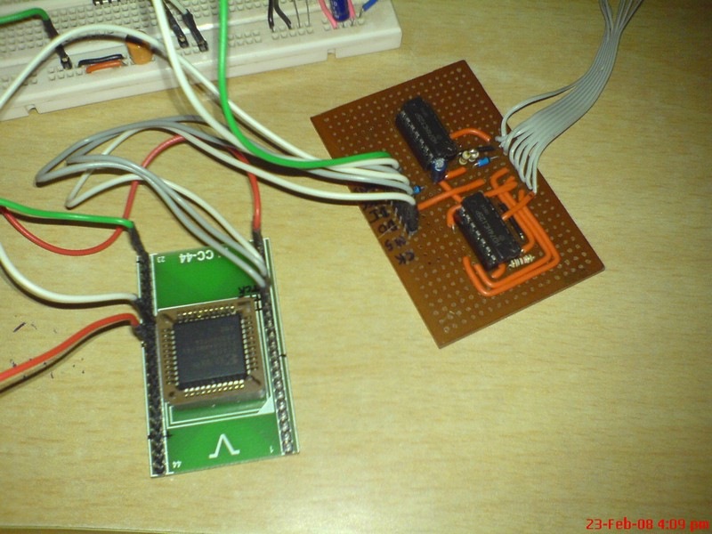
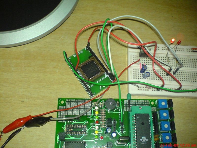
Now connect three wires to pin1,pin2 and pin3 of CPLD. As we have specified, pin1 is clock, pin2 is MSB of count and pin3 is LSB of count. Connect two LEDs with 470E series resistance to pin2 and pin3. Give clock input to pin1 by simple switch / using microcontroller / using signal generator and observe the output.
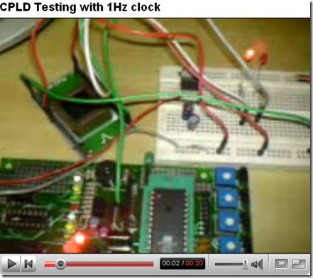
| This shows my test results. I have used my AVR development board to generate 1Hz clock. |

Trouble shooting
– CPLD getting HOT : you have reversed VCC and GND connections / applied more than 5V to VCC pins.
– CPLD not getting detected in iMPACT : Check all connections / JTAG cable is not powered up / CPLD is not powered up / Length of cable between LPT port and JTAG circuit is more than 2Ft / other pins of CPLD are connected to LEDs or VCC or GND. For proper programming only connect VCC, GND and JTAG pins of CPLD, remove all other connections.
– Program is not getting executed properly : Problem with clock. Give proper SQUARE wave waveform as a clock using another micro or signal generator.
Download complete code from here .
…. And finally, if you found this tutorial helpful or have any suggestions … do leave a comment.